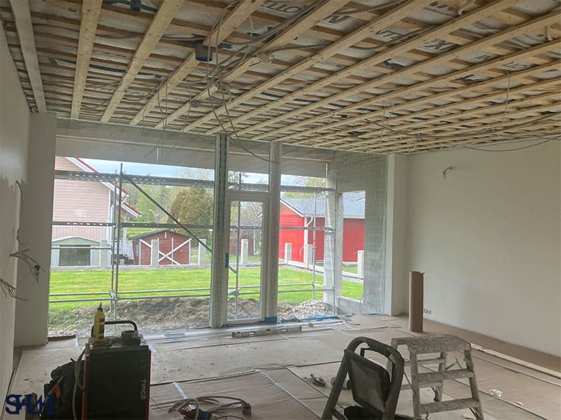
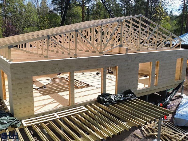
Concrete Structure Design is the highly specialized discipline governing the analysis, dimensioning, and detailing of structures made from reinforced concrete (RC). As the world’s most widely used building material, RC provides unparalleled versatility, durability, and fire resistance, making it essential for high-rise buildings, critical infrastructure, and complex architectural forms.

Analyzing compressive strength, elastic modulus, and time-dependent creep to strictly control structural deflection and cracking.
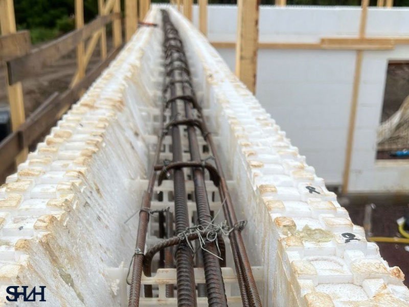
Designing tension-controlled longitudinal steel and precise stirrup spacing to prevent sudden, brittle shear failures.
Mapping biaxial bending combinations and calculating P-Delta secondary moments to secure high-rise frame stability.
Engineering flat slabs with dedicated shear studs and rigid diaphragm action to safely distribute lateral wind and seismic forces.
Detailing strong-column/weak-beam joints and boundary elements to ensure ductile energy dissipation during earthquakes.
Designing high-capacity lap splices, embedded steel plates, and mechanical connectors for hybrid timber or steel interfaces.
Our clients rely on us for accurate engineering, practical solutions and dependable project delivery.

“The project went very smoothly! The structural design information we had was very limited, yet Ahmad was able to expertly design the steel structures based on that. The measurements were precise, and it was a big plus that he improved the structural connections to better suit the needs of the construction site.”
“Our project involved acting as the structural engineer for the house and carrying out the foundation design. Ahmad worked professionally, and whenever something was needed, he always took care of it quickly. He was easy to reach by both phone and email. Working with him was easy and pleasant. I can definitely recommend him!”
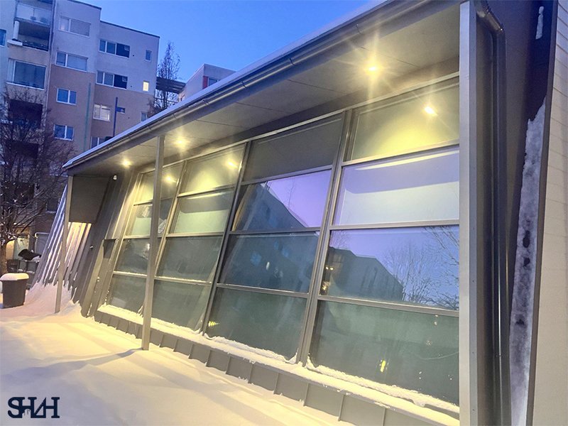
“The canopy design was completed well on schedule, and the designer was readily available also during the tendering phase.”
“Renovation project of a solid-frame shoreline pier. Design of drilled piles for difficult soil conditions. The work progressed swiftly in terms of planning, taking into account both the client’s and the contractor’s perspectives.”
“Excellent and customer-oriented service. The designer was easily reachable throughout the project, and advice or clarifications were provided almost immediately whenever something was unclear.”
“Shah designed and developed a technical calculation program for us. The service was professional, and the work was completed within the agreed schedule.”
“Excellent service and genuine interest in the customer’s project. In our case, a lot of cost optimization was done, and the impact of different solution options on the overall project was always clearly explained, making decision-making easier. All questions were always answered.”
“A highly accessible and responsible designer.”
“The service was very fast and solution-oriented, even with more demanding structural challenges. Quick accessibility via phone, email, or face-to-face meetings was excellent.”
At Shah.fi, our Concrete Structure Design service transcends basic code minimums. We focus on optimizing material efficiency, rigorously controlling serviceability limit states (such as excessive cracking and long-term deflection), and ensuring the structure exhibits ductile behavior—a paramount safety requirement in high-seismic regions. This guide details the comprehensive, code-driven technical process, from material science to advanced connection detailing, that guarantees a superior, resilient RC design.
The choice of structural system profoundly impacts a project’s lifecycle. To explore how we integrate this specialized field into the overall project framework and design philosophy, view our complete overview of Structural Design services and technical expertise.
A precise understanding of the components—concrete and steel—and the governing design codes is the absolute foundation of accurate RC design.
Concrete design is governed by properties measured at specific ages:
Steel reinforcement provides the tensile capacity and ductility that concrete inherently lacks. Designers select steel based on its yield strength.
Modern RC design strictly adheres to the Load and Resistance Factor Design (LRFD) or Ultimate Strength Design (USD) methods, as mandated by ACI 318 or Eurocode 2.
Concrete beams are the primary horizontal elements, designed to safely resist the bending moment and shear forces derived from the structural analysis.
Flexural design determines the precise area of longitudinal steel reinforcement required to withstand the bending moment.
Shear failure is typically sudden and brittle, making robust shear design paramount. The nominal shear strength is the sum of the concrete’s contribution and the shear reinforcement (stirrups) contribution
A serviceable structure performs adequately under normal working loads (unfactored loads):
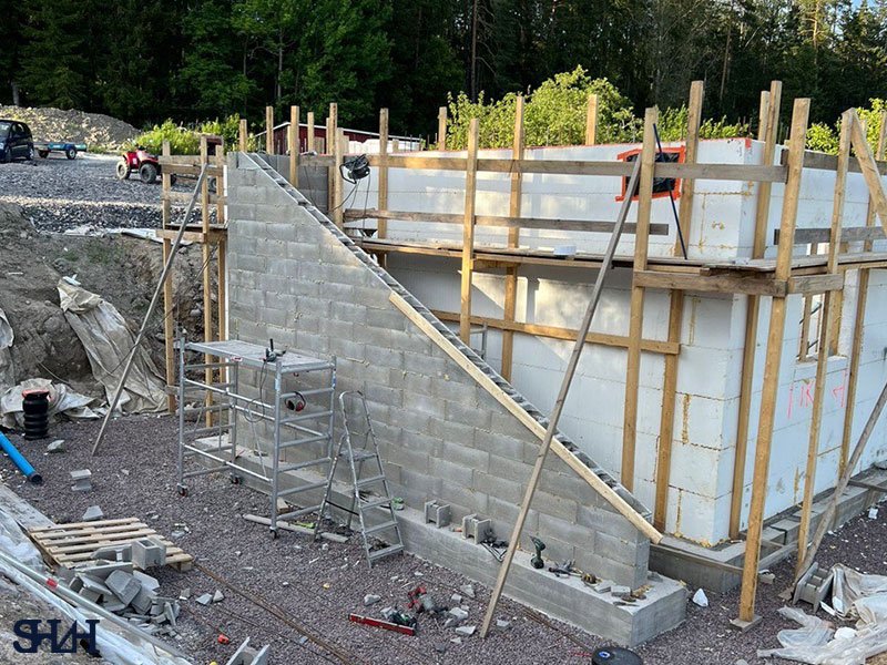
Columns and slabs are central to vertical load transfer and horizontal stability.
Columns are primarily designed for combined axial load and bending moment.
Tall, slender columns can fail prematurely due to secondary moments caused by deformation. The P-Delta effect (axial load P multiplied by lateral deflection $\Delta$) must be accurately modeled and factored into the design by magnifying the primary moments. This stability analysis is crucial for high-rise RC frames.
In high-seismic regions, Concrete Structure Design must rigidly adhere to Capacity Design Principles to ensure ductile, stable behavior during an earthquake.
Shear walls are stiff, vertical elements that efficiently resist lateral forces. Their design involves complex analysis for combined axial load, shear, and overturning moment.
The core principle is to ensure that plastic hinges (the designed points of yielding) form in the beams rather than the columns or beam-column joints. This ensures that the building maintains its vertical load-carrying capacity even after significant structural damage from an earthquake.
The choice between a concrete shear wall system and a steel braced frame is critical. Compare the seismic performance, construction speed, and complexity of concrete systems with Advanced Steel Structure Design Principles and Connection Engineering.
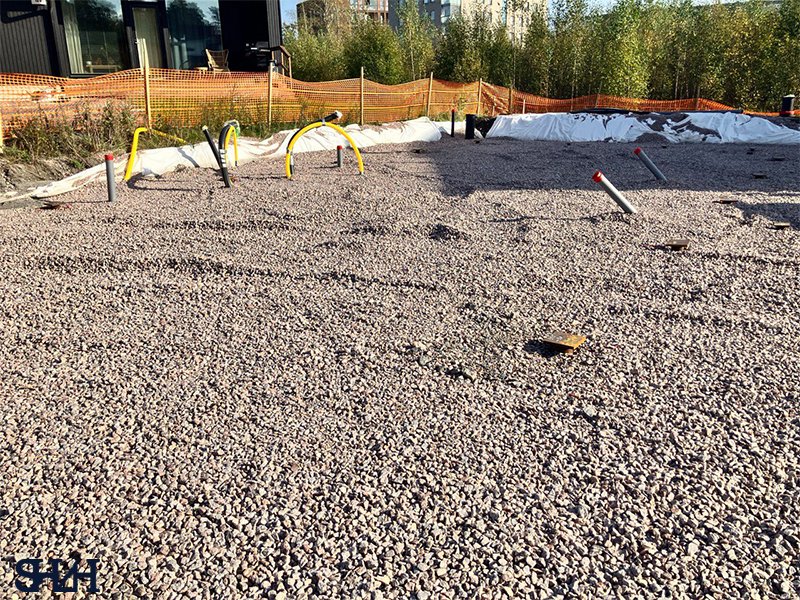
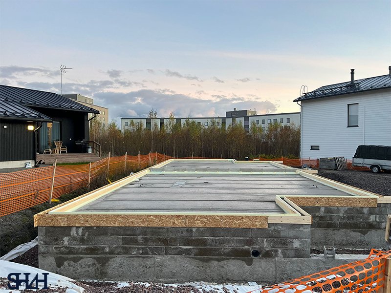
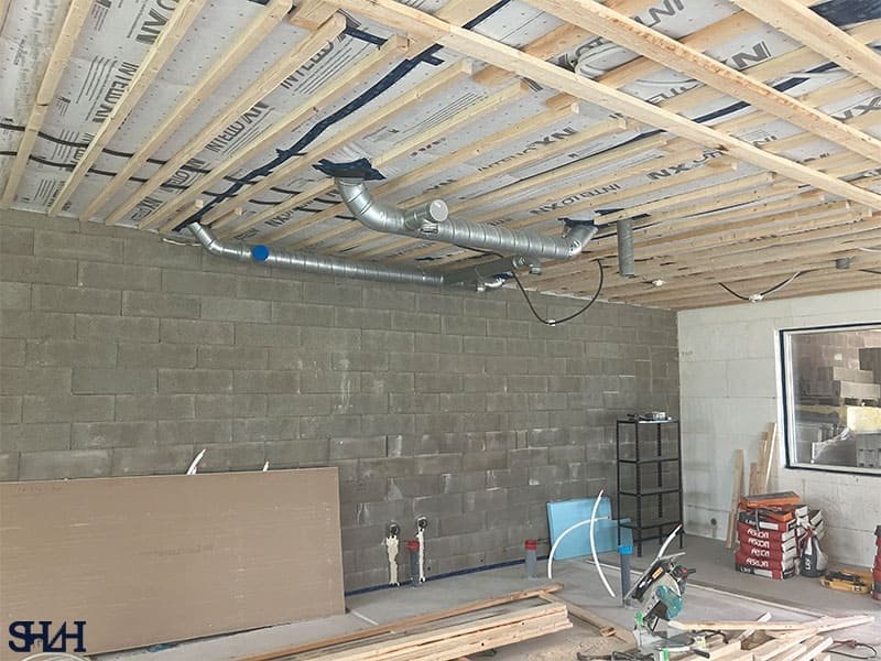
The integrity of the structure depends on seamless, robust connections between elements and proper interaction with the ground.
The load transfer between the concrete column and its foundation is ensured via dowel bars (or starter bars).
The base of the design relies on the soil. The structural size of the foundation required to resist the column forces (especially high shear and moment from seismic loading) is determined by the analysis detailed in The Ultimate Guide to Foundation Design and Geotechnical Engineering.
When concrete meets other materials, specific interface design is required:
Learn about the complex connections required to integrate concrete cores with sustainable wood elements in our resource on The Future of Timber Structure Design and Mass Timber Construction.
Industrial facilities, unlike residential buildings, subject concrete slabs and frames to specific extreme loads:
While the superstructure may be steel, the industrial foundation and ground slab are almost always concrete. Reviewing the specialized heavy loadings for these facilities is covered in Expert Guide to Steel Hall Design and Fabrication.
Final detailing must ensure constructability:
Concrete Structure Design is a high-stakes, code-driven discipline demanding technical precision. From determining the optimum concrete mix to detailing the seismic confinement, every step must adhere to rigorous standards to guarantee public safety and structural longevity.
By choosing Shah.fi, you partner with experts who utilize advanced analysis, implement strict capacity design principles, and deliver a resilient, optimized structural framework. Our focus on durability and constructability ensures your project is cost-efficient both during construction and over its lifetime.
The difference between an ordinary building and an iconic one is rarely the budget or the materials—it's the vision behind it.
Bring us your ideas, sketches, challenges, or even unfinished thoughts. We'll help shape them into spaces that are intelligent, functional, and unforgettable.
Your next landmark begins here.Talk to Our Experts — Free Initial Consultation.
Our Location
Tiistilänkuja 5 ,Espoo, Finland

 Call
Call Contact
 E-mail

